Digitising the track
Once we have prepared the map and imported terrain we are ready to start laying track.
- Open the digitiser, load the previously prepared session and scroll to the area we want to start laying track in.
- Select the track tool (single or double line) from the toolbar.
- Click on the map to mark the line of the track.
When you have finished marking the track, click the commit button ("!")
The track tool dialog opens:
- Select "Single Line" or "Double Line" as required, and click "Lay track at terrain elevation"
- You an also lay track at a specific elevation if required - but in the case we want the terrain to be at the terrain level.
- Click "OK"
- The digitiser lays track along the marked routes.
- Find the track in the main Rail3D window.
- (Hint, it is useful to mark a position in the layout, but using the "T" tool in the digitiser to mark a location. You can then use "Goto" in the main window to go to that location)
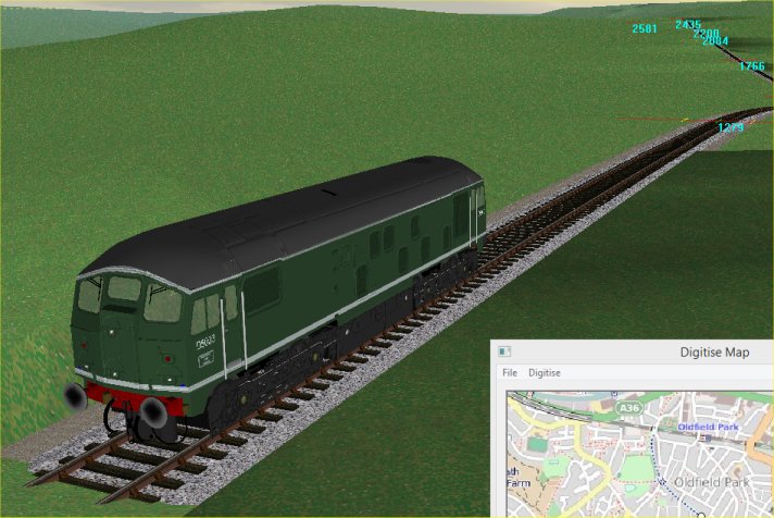
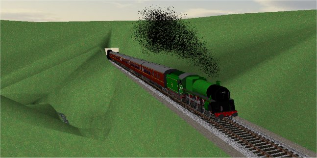
I like to place a train on the track at this point: I can then view the terrain from the train angle, and can move the train along the track:
The digitiser lays track at the terrain level, so will need some adjusting:
- the elevation needs to be adjusted to produce cuttings and embankments
- some sections need to be straightened (the digitiser rarely produces straight track)
The first thing to do is straighten the track where needed and adjust curves. To straighten track, we use the marker tools to mark the ends of the section of track we want to straighten, and use the "Straighten between markers" tool to straighten the track.
Adjusting the gradients
We also need to adjust the gradients. As laid by the digitiser, the track will have some very unrealistic gradients, since every point will be at the terrain surface. We actually want some in cuttings, some on embankments and some in tunnels.
We don't usually need to adjust every node - the best way to set the elevations is to set the elevation of key points, place the markers at the ends to the line (or the stretch we want to work on) and use the "Grade between markers" tool.
It is very helpful to have a gradient profile, or other information about elevations to set the heights. There is a profile for this section of line at http://www.twotunnels.org.uk/graphics/sad-mid-profile.jpg
From this it is possible to calculate the heights and set the nodes along the line.

We can calculate the elevations as follows.
- To start we need to know at least one elevation, or if we don't know it, we need to be able to make a good estimate.
- In this case, I don't have any known elevations, but from close examination of the relevant ordnance survey maps, I can determine the elevation of Bath Green Park as 20m.
So, we can now work down the line and calculate elevations from the gradient profile above
- Bath elevation is 20m. From Bath to Bath Jct is level, so Bath Jct elevation is 20m
- The next stretch from Bath Jct is 0.75 miles at 1 in 50. 0.75 miles is 1207 metres. 1207/50 = 24.1, so the elevation at the end of this stretch is 44.1 metres
- The next stretch is level for 0.16 miles. The elevation at the end is 44.1 metres
- Next we have 0.22 miles at 1 in 66. 0.22 miles is 354metres, so the elevation change is 356/66 = 5.4 metres. The end elevation will be 49.5 metres.
and so on ....
Obviously this is a case for a spreadsheet:
Accuracy is essential. Because the elevations are worked out down the line, any errors will be cumulative.
When I first calculated the elevations of this stretch, I misread the -55 stretch after Coombe Down Tunnel. The effect of this further south was to put the track about 20 metres above the terrain level, whcih was obviously wrong.
Check, check and check again. And find the most detailed/accurate gradient/height elevation possible. I was originally working from a less-detailed gradient profile which did not show some of the shorter stretches, finding this more detailed diagram made quite a difference to the outcome.
Setting the elevation
Once we have calculated the elevations, we need to apply them to the track.
We can use the "Grade between markers" tool to set the grades and elevations over a stretch at a time.
Move to the point in the layout that matches the 0 distance of our calculations (in my spreadsheet above, the 0 is at Bath Jct)
- Select the node at the zero (datum) point.
- Set the node elevation to the known (or determined elevation) and tick "Lock" to lock the elevation
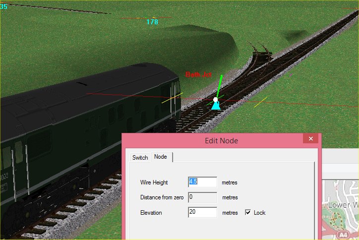
- With the node selected, select "Mark Zero Point" from the "Tools" menu
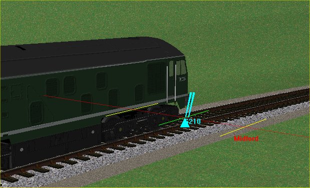
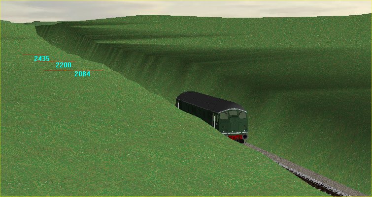
- Select "Show Distance from Zero" from the "Tools" menu
- Rail3d now marks each node with the distance from the datum (or zero) point (as shown above)
- Place marker 1 on the zero node by using "Set Marker 1" from the "Tools" menu
we now need to move to the next point in our list of elevations (see spreadsheet), this is at 1207 metres.
- With a train/loco on the track (and going in the right direction!) Select "Run Train to distance" from the "Tools" menu
- In the dialog that opens, enter the distance "1207" and click "OK"
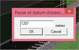
- The train will now run to the specifed distance, and stop at (approximatly) 1207 metres distance.
- If there is a node at or near this postion, you can use that node. If there is no node, use "Insert Node" to create a new node.
- Set the elevation of the node to the desired elevation and tick the "lock" box.
- Use the "Run to Distance" tool (press "F12") to go the next distance point .... repeat as necessary
Continue along as long a stretch of track as you want to do. You can do many kilometres of track at once, but it is worth doing a short stretch of track (maybe 10-20km) at a time.
- When you have got to the other end of the stretch you are working on, select the final node and set its elevation
- Set Marker 2 using "Set Marker 2" from the "Tools" menu.
- Use "Grade between markers" to grade the track between the two points set.
- Rebuild the terrain ("Generate Terrain" from the "Scenery" menu, or the toolbar)
Reverse the train, and run back over the section to check the result, there will be several things needing adjustment.
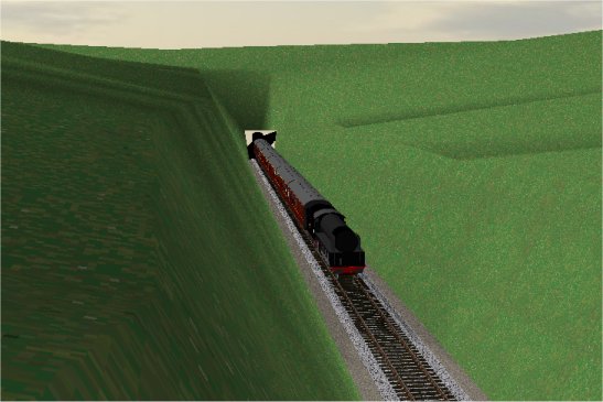
- Tunnels
- We haven't set any tunnels yet, so there will be deep cuttings where there should be tunnels:
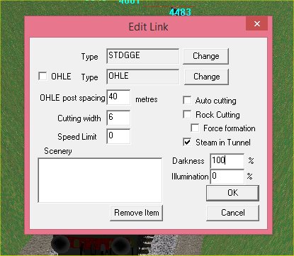
- Edit the link, and change the track to tunnel by unticking "Auto Cutting", ticking "Steam in tunnel" and setting darkness to "100"
- You could also add a suitable tunnel scenery model at the same time
- Cuttings and embankments
- There will be places where the track is in a cutting or an embankment, and shouldn't be:
- This happens where the accuracy of the DEM data (at 90 metre pitch) is not good enough to get the exact terrain shape in the area, or there are errors in the terrain height.
- You will need to adjust the terrain points.
- Use the "Erase Terrain" tool to remove terrain points that are causing problems
- Use "Add Terrain" tool to create new terrain points as required
- Use "Stitch Terrain" to create new terrain points at the same elevation as the track where necessary.
- Terrain points on the track
- You will often need to remove or adjust terrain points close to or on the track:
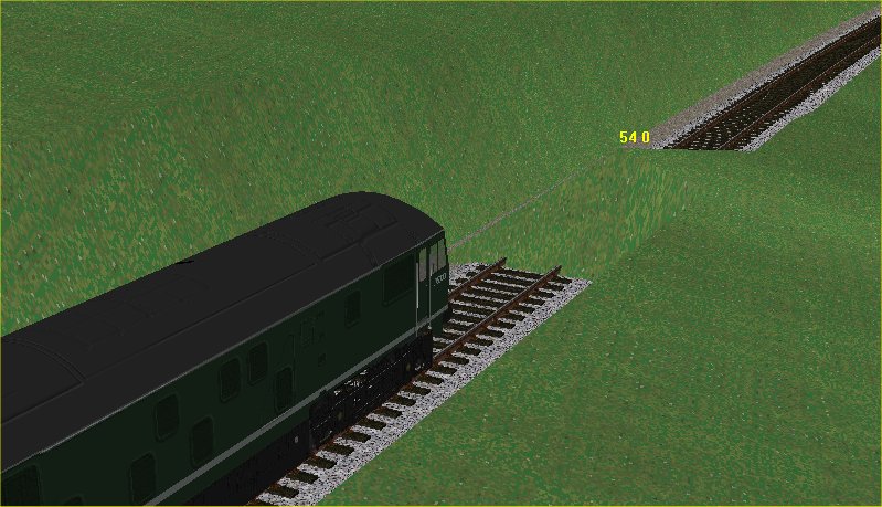
- Here there is a terrain point on the track and slightly too high.
- Erase the terrain point and replace with a new point at the track elevation (Use "stitch terrain to track" from the right-click scenery sub-menu) or create new points to the side of the track
- You can also use the Terrain Setting Train tool to adjust the heights of terrain points on the track automatically.
Notes
- It usually takes several passes over a given stretch of line to achieve a satisfactory result, adjusting node positions, making sections straight, or adjusting curves and adjusting elevations as required. You shouldn't try to do too long a stretch at a time.
- Always start by laying a single line and get the elevations and alignment of this line correct before adding points, loops and sidings. Although it is tempting to add switches etc, once you do, it becomes much harder to adjust elevation and line, so it is worth getting a single line of track correct before you add the detail
- When laying double track routes, it is still worth laying a single line first, adjusting this until it is correct before adding the second line. The "Quick Track" tool is a quick and easy way to add the second line.
Example of terrain adjustment - Lyncombe Vale.
A typical example of where the DEM data just isn't good enough is Lyncombe Vale, here it is in the layout:
Compare with this view taken near the same position (from http://www.twotunnels.org.uk/image_lyncombe_2.html)

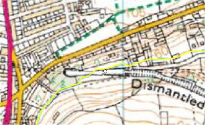
See also the map at http://maps.nls.uk/geo/explore/#zoom=16&lat=51.36985&lon=-2.3565&layers=10 and compare it with the DEM terrain points imported:
The prominent contour on the map (near the bridge under the railway) is 200ft - or 61 metres. The DEM data has clearly not picked up this little valley. This could be due to a number of reasons, including tree cover, the spacing of the 90 metre grid points etc.
Either way, I need to recreate the vale to get the layout to look right.
So, I'm going to do this by adding the little stream that flows down the vale. In the digitiser I can just about pick out the stream - it's not as clear as on the 1960s map - and I click along it to create the stream using the "Brook" track type (and a narrow cutting width of 1 metre)
and I click the commit (!) button to create the brook in the layout.
Now I'm going to move along the brook I've just created setting the elevation where the brook crosses a contour line. (And using both the old 1960s map and the modern metric map to check).
Once I've set the contour points, I can put the markers at each end of the length of brook and use "Grade between markers" to grade the brook.
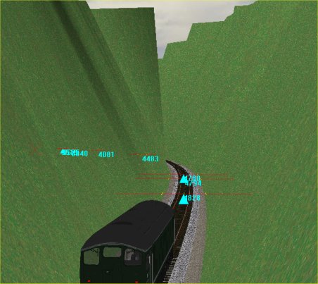
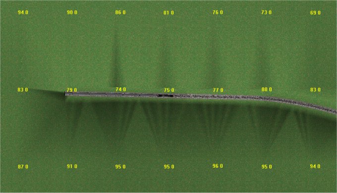
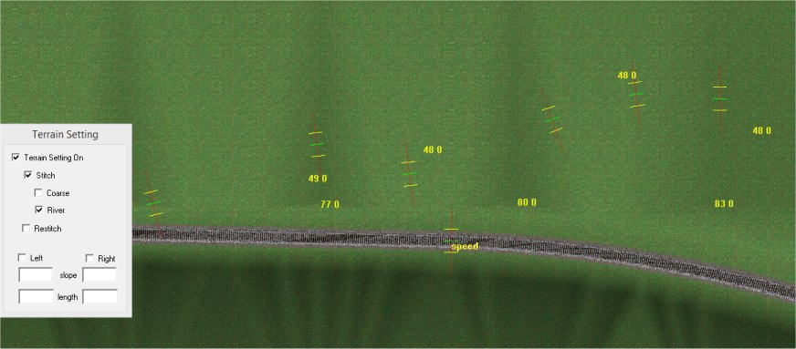
When I'm happy with the position and elevation of the brook, I run a "train" along it (usually I use a Landrover for this) and use the Terrain Setting tool in river mode to create terrain points.
OK, that's getting there, but there are still some points (the 77, 80 and 83 in the shot above) that are wrong, so I'm just going to delete those points.
So, I can now retriangulate and see what it looks like.
Ok, that's better (possibly too deep - so I need to check the contours again and make sure I've got it right). I'm going to tweak it a bit by adding a few more points to adjust the width of the valley bottom.
Next Steps
Once I'm happy with the general line of the track (straights and curves) and the gradients and elevations, I can add the second line (if appropriate) and move onto the detail of stations and sidings: Fine Tuning
Tutorials
MRG 15/02/2015 14:41:42