Grades And Vertical Curves
(:num:)
Rail3D has good support for building track that includes gradients. The main tool for working with gradients is Grade Between Markers.
1 Basic Grading
Start with the gradient profile of the line you are modelling (if you don’t have a gradient profile like the one below, you will have to pick out the elevation of key points on the line from the map).
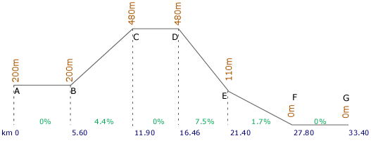
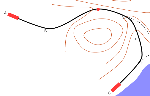
- Lay the track from A to G in the usual way with the Digitiser Tool, setting the start elevation as 200m and the end elevation as 0m. Make sure that you have placed nodes at least at the points on the map corresponding to each of the points A to G on the gradient profile.
- Use the Digitiser to place text labels at the points A to G.
- In the main Rail3D screen, have a look at the track you’ve laid (using a test train helps) and tidy up the track produced by the Digitiser (see Laying Nice Curves for some tips on this). Don’t start adding stations and junctions yet, though.
- Once you’re reasonably happy with the track-laying, use Goto Text Label to move to each of the labels in turn.
- Double-click the node to open its properties dialogue
- Set the node elevation to the correct value as shown on the profile
- Check Lock node
-
- The node is marked with a circle to show that it is locked. The track will probably look rather ike a roller-coaster at this point — don’t worry about it, we’re going to fix that!
- When you have set and locked the node elevations for points A to G, goto point A and set Marker 1 there. Set Marker 2 at point G.
- Run Grade Between Markers leaving the options at their default values.
- All the nodes you have not locked will be shifted vertically to the correct elevations using interpolation between the elevations of the locked nodes.
- Now you can put in the additional trackwork at stations and junctions.
2 How to create smooth vertical curves
Using the standard approach to grading described above produces good results for railways with sensible gradients, but is a bit problematic if you have big gradient changes, e.g. on rack lines where you might have transitions from 20% to near-level and back again at stations.
2.1 Grade Between Markers
Grade Between Markers is just a linear interpolation, i.e. it adjusts the elevation of the unlocked nodes to produce a series of straight-line sections on the gradient profile, with sharp changes of slope at the locked nodes.
2.2 Vertical Curves
Rail3D works out suitable node angles to fit vertical Bezier curves between the nodes, in much the same way as it draws horizontal curves. The slope of intermediate points is smoothed to be parallel to the line between the two points either side. Thus:
However, we found this produced odd effects at the end of level stretches, so the rule is modified to include “if the point is at one end of a level stretch, the slope of the point is level”. Like this:
2.3 Problems with vertical curves
Because the track has to pass through the point of intersection of the two gradients (there is a locked node there), you can’t get a nice smooth vertical curve: there always has to be some overshoot somewhere. This means that when you’re approaching a transition from uphill to level, there is a sort of S-curve, with the gradient steepening as you approach the final node, then levelling out quite sharply.
The program has recognised that section cd is meant to be level, and has set the vertical angle at node C to zero. This means that the overshoot is all on the downhill side, where it is less obvious than it would be on the level section. But if the slope bc is steep, the overshoot can still be rather unrealistic.
See the discussion of Bezier properties in the User Guide for more on this sort of thing
Having worked all this out, the solution is blindingly obvious - blend out the node at the break of grade, and you will get a sensible transition curve. So in practice you would insert an extra locked node, C’, which extends your level section a bit, then perform Grade Between Markers, then blend out the extra node.
(This isn’t quite perfect — because of the way Rail3D calculates the node angles you’ll now get a small overshoot at the node before the change of slope, as shown in the diagram above, but it probably won’t be visible to the naked eye.)
Note: if you use this solution, be careful to put node C’ back again if you ever need to rerun Grade Between Markers, otherwise you’ll be back where you started!
loneaussie 13/02/2015 22:26:27